sabato, novembre 29, 2014

Insert Excel worksheets as Revit Schedules

I'm ve been away for a while, I've some news too.
Since October the 1st 2014 I'm part of the Autodesk Consulting AEC EMEA team, and I'm really happy! I'm sorrounded by very talented people and I'm learning everyday something new. Unfortunately I wasn't able to blog for a long time.

But anyway I'm here now and I want to share with you what I couldn.t over a year ago. During the first session in the very first RTC Europe in Delft, David Conant showed us a very interesting application of the new feature in Revit 2014, the highly customizable schedules!
Back at the time I had little knowledge of coding since I had just started the course by Harry Mattison of Boost Your BIM on Udemy, which by the way you should totally check out if you haven't yet.

I had time these days to test my understanding of how Revit API can work for me and made a little experiment to mimic what I saw at RTC, it's still a work in progress but I think it's been one of the highlights of that a RTC and shows pretty well what can be ddone if you just think out of the box, so my big thank you goes to David and Harry.

Here it is.


giovedì, settembre 25, 2014

Export Sheets in shared coordinates

When working with consultants or clients it's fairly common to ship PDFs and DWGs of the sheet sets along with the Revit model, however DWGs are the weakest part of the overall process.
Revit is not able, natively, to export DWG in shared coordiantes from a sheet view, but from a regular model view it does although it will never be a native DWG file. So I wrote a macro (see a previous post) that collects the views on a sheet and exports them in a separate folder to have them organized and in shared coordinates.
What was missing was the ability to include the title block, which was ok for consultants but not for the client.
So here's a video that shows how this issue can be solved using both Revit and AutoCAD.
DWGs are still X-Refs and they are not clipped like in the previous version, each view is then rotated accordingly to the Revit file. Each viewport only shows the layers of the corresponding x-ref. For further enhancements the views could be locked automatically, there could be a batch file that will open AutoCAD and do the job for each sheet file, etc... I'm still working on and testing it. I hope to find a way to run the whole thing from Revit with the press of a button. Suggestions and critiques are appreciated as long as they are constructive.


lunedì, settembre 22, 2014

Super Tag - Parameters grouping


In this examples I'm trying to retrieve the parameters of a generic model representing a person (a generic model smile shaped) in a room with all the equipment that belongs to his/her such as the workstation or the phone (each family has its own parameters).
In the previous example parameters were just listed in a certain order hard-coded in the Updater, this time the order needs to change slightly so that the parameters referring to a spefic person are all consequential.
In order to do this an additional step must be included in the process.
The best way I could think of is to group the families involved (the person, the workstation and the phone), retrieve the parameters for grouped objects first and then the remaining outside of groups.

mercoledì, settembre 17, 2014

Super Tag - Dynamic Model Update


I've been wrapping my head around dynamic model update in order to push my code further to be more "Revit-ish", so it updates instantly and has no longer a "fire and forget" sort of behaviour.
I've implemented an IUpdater interface that loops through the family instances, reads their parameters in a certain order and then pushes them into the comments of the room.
It's not perfectly Revit since it's not bi-directional at the moment, anyway it gets the job done nicely.

Technically the oddest part in developing this idea was to realize that an IUpdater doesn't need a transaction to work.

Applications are endless, this one I called "Super Tag", it would give the ability to the users to push calculated values into tags (finally!), embedding a piece of code in the template file assuring that everyone on the team has the same tools available.

There are considerations to make on performances, but it sure is a great thing we have to suit our design.

sabato, settembre 06, 2014

Dynamo - Document Nodes Confusion

In addition to Marcello's post  on confusing node names for selection in Dynamo, I'd like to point out what I've just discovered about the Document nodes.

In the API the document that is shown to the user is called Active UIDocument (for brevity uidoc), this element has a property called "Document" that refers to the data base level document (for brevity doc). Any time we want to edit a file in Revit we need to open a transaction that points to a specific doc, while the user interacts with the current uidoc.
In a Revit session there could be multiple docs opened at the same time at a database level (think for instance to a host and links scenario, linked files are documents somehow opened at a database level but not directly editable by the user in the current session; similarly, with multiple editable docs opened, the user is allowed to edit just one at a time, the active document, the uidoc), they could be project or family documents.
The API allows access to those docs without the user interaction and for this reason it's important to have clear in mind the differences between the two: for example, object selections belong to the uidoc (because they require the user intervention), walltypes belong to the doc (because their definition doesn't depend on variables such as the active view), etc.


In the picture above you can see that Document.Current is referring to the UIDocument since I got the active view name, while the Element.Document is referring to the Document since I got the title.
Hope this is gonna be fixed or cleared up in releases to come.


Are you kidding me???


venerdì, settembre 05, 2014

Dynamo - Rooms Solids - Color Scheme for any parameter

This is a further development of previous Dynamo definition, now it can apply the color scheme for any parameter, there's a little bit of coding in there because I couldn't figure out why a cross product lacing over a List.FilterByBoolMask returned a null list for the In and Out output ports.
Anyway I did it myself using a very simple script in Python.
I'm trying to avoid them as much as I can, really, but when I'm tight on the dead line and I need  the get the job done, coding is always my best option, even if I don't feel particularly comfortable with Python, but I guess it's how my brain works, I know for a fact that amazing things are achievable just using the OutOfTheBox set of nodes, so I hope to have enough time to obtain the same thing using a "pure nodes" approach instead.

I guess that the beauty of Dynamo is that everybody can play with it and  make his own tools, no doubt about that.

Here's the code I've used to collect rooms in the project:


Here's the code I've used to retrieve indexes evaluating the elements of ListA against the elements of a ListB, the output is a list of integers, as long as ListA.
In this example ListA contains Department values for each room in the project (11 rooms gives 11 items) while ListB contains the same values but derived from the Color Scheme file (5 department entries gives 5 items).


The outcome of this python script is used to determine which color has to be used to override each one of  the solids derived from rooms.

Solid extraction and ListA:


Color override and ListB:


Here's a .Zip file containing the .Dyn, .Rvt and .Csv used in this example.
In action:


giovedì, settembre 04, 2014

Music as a Language: Victor Wooten at TEDxGabriolaIsland

One of the greatest musicians of our times, Victor Wooten gives a speach at TEDx on what music is for him, sharing his experience and some interesting thoughts on life.
Enjoy.

mercoledì, settembre 03, 2014

Dynamo Room Solids


I've been asked today by a collegue how to replicate an axonometric view of AutoCAD spaces into Revit for a preliminary design.
In the past I've tried to do something using IFC but the result wasn't that good after all for many reasons.
This time I tried a Dynamo approach to the problem since it allows access to data and particulary to the solid representation of elements.
What I needed was a little bit of code to select rooms in the project but I still suck in Python, I happend by chance in a package by Nathan Miller called LunchBox and one of the custom nodes inside this package retrieves a lot of room data. What I did in this case was to copy the import statements from this node and write a few lines of Python code on my own to filter objects belonging to the Room Category.
After that it was fairly simple extract the solid representation for each room, I created a list to keep the geometries distinct because I wanted to be able to control the color of each room to match the color scheme in 2D views.
Here comes the sloppy part: unfortunately the API (Revit 2014 as far as I know) still doesn't give access to the color scheme parameters, so not even in Dynamo it shouldn't be possible to retrieve those parameters.
To keep it simple I decided to write a CSV file containing the paramter value and the components for the colors in the color scheme (this one was based on the name of the room, but it could be done for every parameter availible, just keep in mind that room solids have to be grouped as one big object for each value of the color scheme (I know it's not very handy but I couldn't figure out another way to do it, suggestions appreaciated).
Here's the definition for those who want to have a closer look to it.

martedì, settembre 02, 2014

LOR - Level Of Reliability

Using acronyms is not really in my culture since I'm not an english mother tongue, it's fairly common though in the rest of the world and I happend to get used to it. I had to be explained what "RAF" stood for in a project based in London, since for me it was Royal Air Force, but the other BIM Manager on the phone told me it was Raised Access Floor, just to name a funny episode that happend to me not too long ago.
Right now the usage of these "magic words" is spreading also in the AEC industry (here's another one).
If everybody understands these acronyms, such as BIM, BEP, VCD and so on, and everybody knows precisely what they refer to there's absolutely no problem with using them.
Unfortunately this is not the case for the subtle LOD (Level of Development), which is sad to note that still too many people tend to confuse with level of detail, which is a completely different concept.
I'd say to shift the attention from the model to the results of the analysis that can be performed on a model at the certain stage of its development.
LOR Level Of Reliability would measure the reliability of those analysis (in a general kind of way), less people would confuse the terminology and the key concepts behind it.
I think at least it is worth a discussion.


domenica, agosto 31, 2014

practical BIM: The Nature of Naming

practical BIM: The Nature of Naming: BIM is by nature a shared environment. For example in the context of Revit each discipline team work together in one file. This new paradig...

venerdì, agosto 29, 2014

Change Elements Workset Macro availible


This is the latest version of this macro that moves objects from one workset to another and let the user check the results via a report button.
The user can copy and paste the Id's in the report for further editing using the Select by Id tool in the ribbon.
There's a check box that allows to move also hidden objects that don't belong to any categories visible to the end user.
Here's the solution to copy in here:

C:\ProgramData\Autodesk\Revit\Macros\2014\Revit\AppHookup

If you're happy with my code please show me some gratitude paying what you want via PayPal to:

puntorevit@gmail.com

giovedì, agosto 28, 2014

Move Elements to Workset - WIP


This macro opens a little form with two drop down  menus listing the worksets in the project and then try to move all the possible object from the source to the target workset.
There's a Log button that opens a read only dialog listing the Id's of the elements and the types divided by workset and the number of objects in parenthesis.
I've used two different techniques to list the worksets in the project, the FilteredWorksetCollector and another one using the WorksetPreviews.
Right now I'm thinking about adding a check list for the categories to move between worksets, so the the form would be something more like the one in this other video:


Implementing the category check list produced some undesirable side effects: Analytical Surfaces and Structural Trusses return an error when selected, categories such as "Other" and "Legend components" are no longer taken into account when performing the macro.
I guess it's best to keep the possibility to control each and every object in the model for the next version.

Dynamo Language Guide for Code Blocks is out!!!


At a first look it seems pretty much the same old Design Script Manual, but it's still crucial in understanding how code blocks work.
Thanks to the team that put this documentation together, you guys are amazing!!!

mercoledì, agosto 27, 2014

Align Topo Macro attempt

Today I've found an interesting Topo add-in by Mustafa Khalil and here's a video demonstrating how it works.

So I decided to understand how it could be done and I tried to mimic the core of the add-in.
My attempt here is really basic, there are no parameters exposed to the user to set for instance.
This exercise gave me the opportunity to understand better some of the topography features in the API, for example the implementation of an interface to manage preprocess failures since it is needed to commit the transaction group necessary to edit a topographic surface.
Another interesting aspect is that Revit won't allow you to process points with the same XY values for topo surfaces, that's why I' decided to add a point at a time while editing the surface.
It would be fun to do the opposite: having a topo and edit the floor secondary element back... oh wait, Marcello Sgambelluri already did it :)


Anyway here you can find the code I've used if you want to have a look at it, if you are happy with it please show me some gratitude paying what you want via PayPal to:

puntorevit@gmail.com

martedì, agosto 26, 2014

Dynamo - 4 Points adaptive component along two lines update for version 0.7.1


When I tried to update the previous definition to the 0.7.1 release something went wrong and Dynamo was stuck.
I took the opportunity to rethink the definition and I found a slightly different approach to the problem: this time I keep the curves as distinct elements almost to the end, this way it's easier to check the orientation of the curves and get rid of the special node for opposite direction of the curves.
After selecting the model lines in the Revit environment Dynamo automatically places the Adaptive component accordingly to the maximum width specified for the subdivision.
If the orientations of the lines are opposite, Dynamo reverses one of the two and perform the definition anyway.

There's always need to delete the panels manually once created like in previous version, it would be nice to have a "dispose" node for this particular goal.
Here's the custom node definition and here's the test definition I've used.

sabato, agosto 23, 2014

Images from the past, hopes for the future

I was looking for some images for a presentation and I came across these pictures of some works I've done at the University prior than 2008, way long before adaptive components came along.
It was definitely fun! but really soon I realized that what I was doing was much, much more than just a 3D model, I saw the potential and what eventually the AEC industry was going to be in the closest future.
That's when I moved my focus from modeling and representation to BIM. Unfortunately most of the people that I know from the University still haven't even approached to BIM and they're just starting now to consider to move, for instance, to Revit because they're blinded by the 3D model and the rendering.

Using Revit to just make a 3d model is like having a Ferrari and use it in the backyard.

So please double check your willingness to learn something new (a BIM approach to design and not just how to use an instrument like Revit), both for productivity on a specific project and in the long run, keep in mind that it can be really painful if you're doing it while you're already working full time but it hasn't necessarely to be a blood bath if you ask for help to competent people.
Break problems into smaller ones, read forums and blogs to find answers to your questions, don't take "no" for an answer and never give up.


martedì, agosto 12, 2014

Dynamo - 3 points Adaptive Component


Today I was emailing with HyunWoo Kim of Enjoy Revit about a possible workflow involving adaptive components.
I made this quick Dynamo exercise on multiple elements selection and a specific 3 points adaptive component.
The 1st and the 2nd point of the family are attached to the ends of the curve while the 3rd is attached to the mid point. The tricky part was to get Dynamo understand the corresponding parameter for the mid point, infact if you insert in the list the value "0.5" directly it returns an error because somehow 5 is passed instead.
But if you use this simple formula c=(a+b)/2, everything seems to work properly.
It also works on curves in a linked DWG.
Here you can find the definition.

UPDATE

The error with 0.5 is no longer an issue since I changed the Operating System settings of the decimal separator for numbers changing them from comma to point.
In order to change it you have to go to Control Panel and click for the location settings, then customize the formats for numbers specifing a point instead of a comma as decimal separator.
Thanks to Colin McCrone and a reader who actually gave me this tip in the comments below.


giovedì, luglio 31, 2014

Family Management Utils - Linked Family Browser


I'm in New York on vacation these days, and the jet lag is still difficult to manage, so I woke up really really early this morning and I did a few experiments with the code I was working on.
I thought it would be nice to have a family browser for linked files, letting the user choose which family types copy into the control file etc...
With this kind of browser the user can visually see which family belongs to each one of the linked files, it would be great to have a search field to filter the tree (just have no idea how to do it right now, I'm still learning).
Next major step will be implement a tab interface for group of settings and objects such as System families, Other families (I've to find a way to separate annotations from model families as the tendenency is to get rid of annotations in linked files), Materials, Filled patterns, Keynotes, View Filters and View templates... of course I know that most of these features are already there with the transfer project standards but, what I'm trying to do, is to reverse the process: instead of doing the transfer for each one of the linked files, I would like to do the same thing from one control file to all the linked files, just once, extending control over non system families and their parameters.
In addition to that there's the visual control of the contents of the model (walls and floors detailed sections, material swatches, doors and windows assemblies, management of family names and type names accordingly to a user defined sequence of parameters/codes).
There's so much to do to make it work properly though.
So here's a my first attempt, what do you think? please let me know in the comments below.


venerdì, luglio 25, 2014

Family Management Utils - WIP


This tool I've developed works on door and window families between different files letting the user edit them inside a single control file and pushing the edited families back to the other files. I've collected a few lines of code and put it all together with a very simple interface.
This is the workflow I've imagined:

  1. Link the different projects into a single control file (CF)
  2. Acquire the families from the linked files cliking on Copy Types
  3. Delete duplicate types if necessary
  4. Create assemblies with 3 main views and dimensions for each type, assigning a unique Type Mark automatically, each assembly is named with this syntax: (TypeMark)_Family_Type
  5. Edit the components as necessary, fill in the data where needed and then update the linked files with the new version
  6. You can finally create assemblies in each linked file for documentation purposes, each assembly is created in the first phase and demolished right in the next phase of the phase sequence, so to not interact with the actual project.
During the process the linked files have to be unloaded, keep in mind that also the family type names shouldn't change before the update, otherwise the tool won't be able to perfomr the update as expected.
For the sake of this example I'm using two linked files, a simple one and a workshared one.
In both cases there are the same door and window families and I'm showing the steps of the workflow, when the linked files are loaded the type mark for the family type in common between the CF and the links can't be changed, this is true for any other parameter such as width, height or material finish.
Once in the linked file a purge unused is recomended.

I still haven't figure out how to dismiss automatically the dialog when reloading families and override the parameters. Any suggestion is appreciated.

lunedì, luglio 21, 2014

Cad Digest


When I started to use Revit in 2006 there were almost no places to find tutorial in italian except for 3dsmile forum, which has now become http://www.RevitForum.com, and I had to find as much material as I could on the internet, basically that's how I learned english.
One of the website I visited the most at the time because it gathers a huge amount of Revit topics, and I still do, was http://www.caddigest.com, and, surprise surprise, this morning I've found a post I wrote a week ago on my blog.
Thanks, really appreciated!

venerdì, luglio 18, 2014

View Depth Override External Command - Bugs Fixed


You can downlaod a zip file containing the .DLL and the .Addin manifest for the external command.
I've to thank a reader for pointing out some issues with the planting category (because previous version didn't take into account categories with no material quantities just like planting).
Also there was another issue with 2D views because the override was performed on a polar distance like in 3D views, now it's been fixed using the distance between the center of the bounding box of an object and the plane of the view.
I discovered that CGS has copied my first idea, and that was basically the goal of me starting to publish the code: to make companies develop better add-ins, but unfortunately this is not the case.
Now you can choose to pay a subscription to them for this tool (along with many others of course), which by the way doesn't work on perspective views while mine does, so why don't use just mine instead of waisting money? please if you're happy with my code show me some gratitude Paying What You Want via PayPal to:

puntorevit@gmail.com

*UPDATE 2015
The command for Revit 2015 works just fine, there's still need for the .addin to reside in the correct folder and the paths inside the file to be eventually updated.
Anyway the addin file should be copied in here:

C:\ProgramData\Autodesk\Revit\Addins\2015

here's the addin file with paths updated for 2015 version.

giovedì, luglio 17, 2014

Delete Family Type Duplicates Macro


when dealing with a lot of copy and paste of objects among files is fairly common to end up with a project browser overpopulated by family types with equal parameters but a different type name (something like 1200x2400mm and 1200x2400mm 2, quite frustrating isn't it?).
For some category such as Doors and Windows the Type mark parameter is automatically changed to be unique to avoid  possible conflicts but all the other parameters remain the same.

Using this macro at your own risk, you can get rid of duplicates in family types.
If you're happy with my code please show me some gratitude Paying What You Want via PayPal to:

puntorevit@gmail.com

lunedì, luglio 14, 2014

Auto Assembly Macro - WIP


In this video I'm showing the results of a macro I'm working on these days that allows to create an assembly for each door and window type present in the project.
It's still a work in progress though, but what it does is pretty clear:

  1. create a generic wall sample to host a family instance of the door / window type
  2. create the family instance
  3. create an assembly with the family instance, its nested shared families and the hosting wall, whose category is after the family category and the name is a combination of the family name and the family type
  4. increase the mark type and assign it to the family type
  5. change the phase of creation and demolition of the assembly to be respectively the first and the second in the sequence
  6. create three assembly views (plan, elevation and section)
  7. create two major dimensions in the elevation view (I'm thinking of an early stage door/window schedule for this development)
There are still issues with curtain wall components though, need to fix that.
Using this method it's possible to create a source file that contains all the families and manage them with type marks, materials, and so on very effectively. Then the necessary editing can be extended to other project files really easily with the concept exposed in the previous post. Getting closer.

Family and Type parameters coordination between documents


Working with linked files brings some advantages on the performances of the computer but it introduces also many coordination issues. Even the same firm can use multiple linked files of the same discipline linked together to split the project into more manageable parts. In that scenario when a component family has to be updated in the geometry and/or the type parameters such as the Type Mark, the Description and so on, it's required the user intervention.
Some operations are really easy to do (for example reload a family), let's say it's just time consuming to open the file, reload and save for each one of the linked files where the family is loaded.
Some others such as filling in the type parameters can be tedious and unfortunately can also introduce coordination errors between the files. This means there's a lot of double checking going on and when there's an issue the user has to manually update the values as many times as the number of the linked files or at least the number of the errors catched by his eye during this process. The basic idea of BIM is to insert data in the model only once and possibly in one place in order to avoid this kind of mistakes.

In the example above I'm demonstrating how it is possible through the API to coordinate two different documents, a source (File1) and a destination document (File2) that share a family (for the sake of the examples it's a furniture family called GEN-1).
In File1 the GEN-1 family has just one type (Type 1)  with all the parameters filled correctly, while in File2 the same family has a different shape, has three types but their parameters have to updated. There's also another family GEN-2 with a Type 1 just to show that it's not involved in the process even if it is a furniture component and has the same Type name.

Notice that the macro can be run even with no document opened. What I'm gonna do next is to create a private method that updates the family content for specified categories (doors, windows, furniture, and all system families such as walls and floors) for all the files linked in a source project.
It's something close to the idea of  the Transfer Project Standards but extended to external families with the ability to override type parameters too.

After the macro has been launched the files are saved, the definition for GEN-1 is the same for both files (rectangular shape) and only Type 1 has been updated to comply with the source file.

This is a little step closer to what I believe to be an ideal tool for Revit project management.

venerdì, luglio 11, 2014

Align Scope Boxes Macro


Every once in a while it happens to deal with small rotations in the project, from structural grids to anything else when the design intent has changed and a new alignment in the building has been introduced.
If you had already set up all your scope boxes for your views it's fine to rotate them but snapping to objects sometimes can be messy and can introduces errors. So I wrote this macro to align a scope box to linear objects such as grids, reference planes, walls or lines. The rotation is performed around the center of the scope box.
This time the code is not that elegant but it gets the job done.

Here you can find the macro. If you're happy with my code, please show me some gratitude Paying What You Want via PayPal to:

puntorevit@gmail.com

giovedì, luglio 10, 2014

Copy Links macro


Inspired by this post by Luke Johnson of What Revit Wants, I thought I could write a macro to achieve the same goal but in a cleaner way, without doing copy/paste gymnastics.
Running this macro will copy all the Revit links from a source document to a destination one from which the macro has been launched while having the documents both opened in the same session.

Here you can find the macro. If you are happy with my code, please show me some gratitude Paying What You Want via PayPal to:

puntorevit@gmail.com

Little Revit to Blender tutorial


After last post I was asked by Julien Benoit to do a tutorial, so here we go, it's not a complete guide but it's a quick overall look of the process, from the installation of the plug-in to the set up of a couple of materials in Blender node editor, hope you like it.

Here you can find the Blender files.

mercoledì, luglio 09, 2014

Free plug-in OBJ Exporter for Revit

I was about to start thinking of it on my own but it's already been done and it's free for 2014 and 2015!


Inglegreen has developed this exporter for Revit, now it is possible to use Blender as an open source external render engine, using the amazing capabilites of the Cycle Renderer (real time rendering) that allows you to do also animations and video editing.


Here's the link to the zip file containing instructions and .dll and .addin manifest.
With this plug-in you'll be able to render your scenes within seconds without using any credits and developing even real world phisics inside your model letting your client exploring it like if it is a video game!


Re-posting: How to deal with Legends in Revit by Mark Twain

I've found this very interesting and useful article by Mark Twain on RevitForum.org blog

I simply report it because it's another step closer to what I believe is a real standard usage of the Revit platform, headed in the same direction of the tools I've been developing lately. There are fair margins for further developments here.

So many thanks to Mark and the Revit community for sharing your knowledge.

How to deal with Legends in Revit

Edited due to remarks made by Forum users. Some pitfalls for the use of Assemblies added in light of honest comparison between the different options.

First of all:

AUTODESK, FIX IT ALREADY!!!! YOU CALL THIS A BIM AUTHORING SOFTWARE? I CAN'T EVEN PROPERLY DOCUMENT THE OBJECTS RESIDING IN MY MODEL, WHETHER IT'S WINDOWS, DOORS OR FREAKIN' TOILET SEATS. THE OOTB LEGEND TOOL IS AN ABSOLUTE TOTAL HEAP OF UTTERLY USELESS CRAP!

And breathe...

But seriously: It's an insult to all of us working on real projects needing to do real documentation. I have been on Revit since version 5.1 and it has been useless as long as I can remember (don't even know if there were Legends on that version, but if there were: they sucked back then too).

Why are legends bad?

1. You can only have a few different views: plan view, front and back elevation. How about sections? How about 3D views?
2. No tagging, no way to extract data from the elements (THAT is the freaking purpose!!!)
3. NO connection to the elements actually used in the model. If an element is deleted, it will remain in the Legend. No way of counting elements.

See image 1.

Image1: Useless crap 

So: useless crap it is... The question is: what should it be like then? There are a few options, listed in order of usability:

1. Phases

The easiest to set up, but also the hardest to manage and check for model compliance.

Image2: Adding Legend Phases 


Image3: Creating Legend Views and setting component Phases 


Image4: Creating a coordination schedule 

- Create two extra Phases: Legend and Demo Legend. Place them before the regular Phases, see image 2.
- Duplicate a Plan View, set Phase to Legend and place your Legend components. Select all Legend components and set the options to Demolish in phase Demo Legend, see image 3.
- Create all Legend views you want and Tag away happily.
- Create a Door schedule with 3 columns: Family and Type and Count. In the Properties screen, Sorting tab, sort by Family and Type. Check off "Itemize every instance". You now have a overview of all types in the model. Now duplicate that schedule and set the Phase to "Legend". You can now compare both schedules side by side to see if all elements are accounted for see image 4.

Pro's:

- Total control over Legend views, tagging, and so on.
- No influence over the model, no need to hide things in regular model views
- It's possible to create schedules to check whether all types are accounted for in the schedule.

Con's:


- Lot of work to set up views.

- No way of distinguishing different instances, there's only a limited amount of parameters that can be used to sort the schedule.
- Needs working knowledge of Phasing
- Needs two schedules and the ability to check them side by side. This could get difficult in large models with lots of types.
- Needs extra "space" in the model to place the Legend components.
- Not very suited for Legend views of multiple components (for instance a room layout, windows with ornaments, window sills and such).


2. Design options

Image5: Adding Design Options 

Image6: Adding elements to a Design Option 

Image7: Setting up coordination schedule 

Image8: Coordination schedule 

A bit harder to set up, but has better ways of checking for Legend-Model consistency:
- Set a Design Option Set called "Legend". Add 2 Options: "Model" and "Legend". See image 5.
- Duplicate a Plan View and place all elements you want to create Legends view from, somewhere outside the model's extents. Due to the setup of the Design Options, they will not be visible in the "normal" model views. See image 6.
- Create all Legend views you want and Tag away happily.
- Create a Door schedule with 3 columns: Family and Type, Mark (or any other text instance parameter) and Count. In the Properties screen, Sorting tab, sort by Family and Type and then by Mark. Check off "Itemize every instance". You now have a overview of all types in the model, see image 7.
- Go to the Legend door, select it, fill out the Mark value as shown in image 8. All the "normal" doors have a blank value.
Image 7 shows us that there is one type in the model that does NOT have a Legend component... This is a fast and reliable way to check whether all TYPES have Legend components. It does not help with instance based deviations...

Pro's:

- Total control over Legend views, tagging, and so on.
- No influence over the model, no need to hide things in regular model views
- It's possible to create schedules to check whether all types are accounted for in the schedule.

Con's:


- Lot of work to set up views.

- No way of distinguishing different instances, there's only a limited amount of parameters that can be used to sort the schedule.
- Needs working knowledge of Design Options
- Needs extra "space" in the model to place the Legend components.
- Not very suited for Legend views of multiple components (for instance a room layout, windows with ornaments, window sills and such).

3. Assemblies

My new favourite, and very close to what the Legend feature should be:

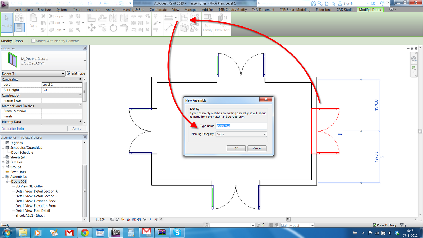
Image9: Creating an Assembly 

- Place your components in the Model. Select a component and choose "Create Assembly" from the contextual tab. Choose an appropriate naming strategy (I use the family + typename which can expand dramatically when you're creating Assemblies from multiple elements), see image 9.


Image10: Selecting Assembly Views 

- Select the Assembly and choose "Create Views" from the contextual tab. Select which views you want, and if they should be placed on a sheet, see image 10. Tag away happily.
- Select next item, repeat the steps above. IF your element matches an existing assembly, it will turn into the same one, see image 11. Best part: this is on instance level! So if you have different instance parameters, it will be a new Assembly. Only problem: when using a unique Mark value to differentiate between different elements of the same kind.

Image11: Duplicate Assemblies are recognised 

- You can tag the Assembly in the model to refer to these Assembly views. Which solves the Mark problem...
- Create a Door schedule as shown in option 1 and 2. Add an extra field "Assembly Name" to check whether all components have been added to an Assembly.

Pro's:

- Legend Views with the click of a mouse button.
- Total control over Legend views, tagging, and so on. Crop Regions can be rotated to meet specific needs
- No influence over the model, no need to hide things in regular model views
- Simply add a column to your object schedules to check whether all types are accounted for in the schedule.
- Recognizes differences on an Instance Level.
- No extra "space" needed in the model to place Legend components
- Suited for Legend Views of multiple components.
- Easy to use workflow.
- (Shared) parameters can be added to assemblies to allow tagging and scheduling.

Con's:


- Instance parameter awareness can be a problem, however this is manageable by adding those parameters to the Assembly itself.

- There's no way to port parameter values from the objects inside an Assembly to the Assembly itself without using the API.
- It would be nice to be able to create Embedded Schedules for Assemblies to have both the Assembly AND the underlying objects in one schedule.
- Most annoying one: you need to manually place all elements in an Assembly one by one. No way to batch-create an Assembly. No way to properly place an Assembly when it's (wall) hosted (try placing an Assembly door...)
- MAJOR BIGGIE: Assemblies do NOT update when changes are applied to instance parameters. WTF??? It recognises differences in instance parameters upon creation, but not when changing them? I thought Revit ALWAYS updated modelled stuff? What the hell kind of cad solution is this?
- Adding objects to an Assembly (for instance, adding a windowsill to a window) creates a new Assembly type. Which is in some ways logical, but also a shame. Verdict on this one is still out...
- Groups cannot be Assembled (is that the correct term?). I get this, I think, because Groups are in many ways similar to Assemblies. I can imagine that these two might collide, but it's not perfect.

Summary
Legends suck. They suck for text notes, they suck for diagrams, and they suck big time for building components. The first two options described here are at best mediocre workarounds with lots of pitfalls and tons of extra work.

Then there were Assemblies... And all was better.
Provided Autodesk fixes a few minor bugs, it is the documenting feature we have been waiting for, for a LONG LONG time.
As far as I'm concerned, Autodesk can delete the Legend tool all together. I will be sticking with Assemblies for Building components from now on (and Generic Annotations for anything else).

HOWEVER: when you're on big projects with lots and lots of types, this solution might not work for you. Because whenever an INSTANCE parameter changes, you'll need to update all Assembly instances in the project. Which sucks big time. It's doable on smaller projects, and it works well when you're changing type parameters. But not when changing INSTANCE parameters. And that is a shortcoming well worth noting. (off course, you could do a "select all instances" > change, but it's the principal of things)

O, I added my sample files to this thread on Revitforum.org.

Happy Reviting,

Mark Twain

martedì, luglio 08, 2014

Material Swatch Macro


This macro goes in the same direction of the previous with the goal of a better management of the projects through the usage of tools that allow the users to save time and visualize better the content of the project.
Generic model families will be generated for each material in the project and their material instance parameter will change automatically.

Here you can find  the code and a file to use with the generic model and the tag used in the example above.

If you're happy with my code, please show me some gratitude Paying What You Want via PayPal to:

puntorevit@gmail.com

lunedì, luglio 07, 2014

Export Shared Coordinates DWGs from Sheets


When you're working with consultants on geo-referenced CAD files what you need to do is to export from your Revit model a CAD in shared coordinates from the views themselves, because, if you do so from the sheets instead, the resulting DWG will be based on project internal coordinates.

What if you have to do that for hundreds, thousands of views? You could run a macro like this one that exports all the views in the sheets as a separate DWG into different folders named after the sheets. Each DWG file name will  have the following syntax:

Sheet number-Viewport detail number.dwg

Then you can zip the folders and send them as background drawings to your consultants. You can customize all the export settings just like from the UI.
It is possible to narrow down the number of sheets to process filtering them by a parameter value of your convenience for example.
These files are not supposed to replace the usual DWGs with the titleblock though.
This could save you some time using Revit.

In order to run the macro, an extra using statement is required:
using System.IO;

If you are happy with my code, please show me some gratitude Paying What You Want via PayPal to:

puntorevit@gmail.com


Category "Other": any ideas?


Sometimes when you deal with worksets you can find some unexplicable objects popultating Workset1 (one of the default worksets created by Revit when the work sharing has been activated).
I wrote a little macro to retrieve in one line all the IDs of the objects grouped by Workset, divided by Instances and Type definitions.

Here's an excerpt of the txt file that you will find on the desktop (I've used notepad++ to show how the rows are built).


Element ID's are placed in one row separated by a semicolon for your convenience when selecting by ID's back in Revit.

Anyway, I can't figure out what this "Other" category stands for, any ideas? There are no good views to show those elements in the working canvas.

You can find the code here.

If you are happy with my code please show me some gratitude Paying What You Want via PayPal to:

puntorevit@gmail.com

domenica, luglio 06, 2014

Love Dynamo


Finally I had the chance to install and test a little bit Dynamo version 0.7.1: definitely love it! thanks guys! Now we are talking.

mercoledì, luglio 02, 2014

Dynamo - Placing adaptive components along two lines


Here's an example of how to use Dynamo to place adaptive components between two lines.
As you can see the surface is quite complex to handle with a sloped glazing and it's way lighter this way rather than with standard curtain panels. I've used 4 points adaptive components that remain flat, lines I've already set up to implement the subdivisions and a couple of Dynamo custom nodes to manage different orientation of the lines.
What is shown in the video is the process I've been using to free Dynamo of the adaptive components.
First select two lines to be processed by the custom node. Once the components are placed there's a lot of copy/paste going on in the Dynamo environment since it retains the ID of the elements it creates.
Deleting the nodes in Dynamo will affect the project but an Undo will restore the adaptive components back on.

Here's a video that shows the structure of the custom node in case of lines with opposite direction: the spacing is set to be 2.5m, I've made a more generic custom node with a length input but it seems to be passed the wrong value and it needs to be fixed inside the custom node.
The family type used could be outside also, I've put it inside just to speed up the process.


What is missing here is a "try and catch" node to let Dynamo decide what custom node is needed depending on the orientation of the lines. Also it would be nice to have a feature that automatically clears the nodes after the definition runs.

Here you can find the definitions of two generic custom nodes.

Crop View By Selection Macro


I've been asked by a  reader if it is possible via Revit API to crop a plan view around a selection of objects, if there are no scope boxes associated it can be done in a fairly easy way.

You can find the code here. If you're happy with my code, please show me some gratitude Paying What You Want via PayPal at:

puntorevit@gmail.com

Hatch to Room 2 - Update


This version of the code takes into account also overlapping arcs, so no more warnings of overlapping objects should pop up when you run the macro (like in previous versions).
To determine if two arcs are overlapping I used the Project() method which projects a XYZ point onto a curve and then I measured the distance between the projected point and the original point (which is one end of the other curve). If the distance is equal to zero (well, a rounded distance at the nineth decimal digit because you never know...), then the curves overlap.
I managed to reverse one of the two arcs to get the proper result which is the shortest arc passing through all the vertices of the two orginal arcs, because the algorythm works if the curves are equally oriented (in other words they share the same normal).

You can find the source here. If you are happy with my code please show me some gratitude Paying What You Want via PayPal to:

puntorevit@gmail.com

lunedì, giugno 30, 2014

Hatch To Room Macro Update


Here's a little improvement to this macro I've been asked recently by a reader of the blog that allows you to get rid of the overlapping lines, at the moment it works only with straight lines though.
Actually the whole idea came to me still while I was developing a macro to optimize floor sketches, something close to what the overkill command does in AutoCAD for those of you that are familiar with this functionality.
What I've been able to accomplish is to check if a pair of curves derived from the hatch boundaries in the CAD file are collinear, overlapping (partially or completely one on top of the other) or joined by one end. If so, the macro creates a new curve (actually a straight line) that can be used in Revit instead, without any warnings showing up.
To achieve that I've used a method that checks for intersections between curves. Unfortunatly it works fine for straight lines but not so well for arcs, I'm still on this particular issue since this method gives you an intersection between arcs that shares the same center point and radius even if they don't actually meet.

You can find the code here and if you're happy with it you can show me some gratitude Paying What You Want on Paypal at:

puntorevit@gmail.com